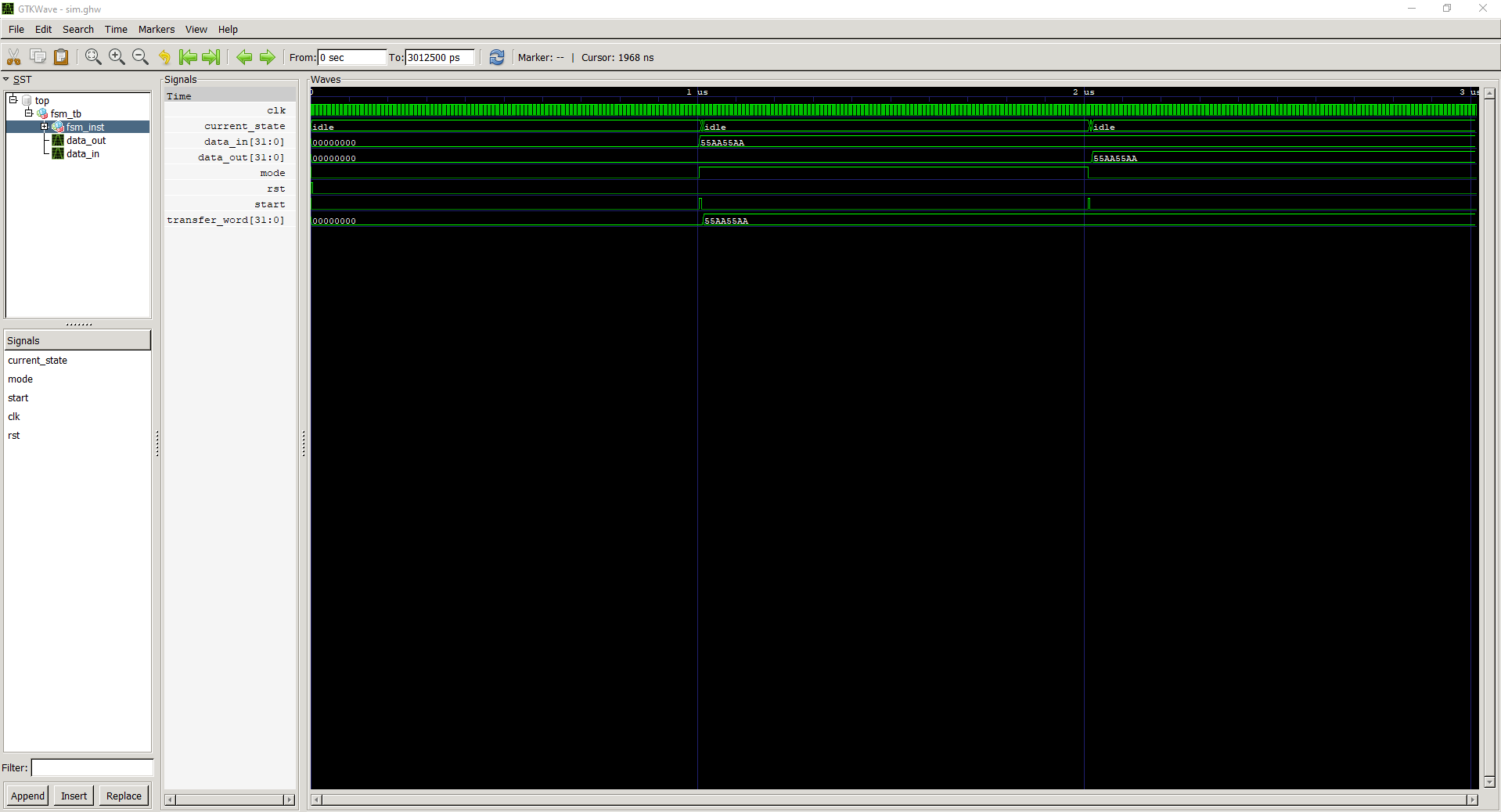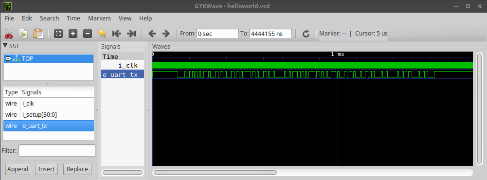

The trigger allows you to control the recording of data, by setting the value of one of the digital analyzer's input pins (D7 by default). Using the Trigger īy default, the logic analyzer records data for the entire duration of the simulation.
DOWNLOAD GTKWAVE FOR WINDOWS SOFTWARE
These software also include powerful protocol analyzers that can decode many common protocols such as UART, I2C, WS2812, and many others. You can use software such as PulseView or GTKWave to open and view the capture files. The file contains the recorded signals in Value Change Dump format. This will download a file called "wokwi-logic.vcd" to your computer. To view the capture, stop the simulation. You should see the green activity LEDs blink as the signals are coming in, and the number of samples show go up.

For instance, if you want to record the I2C communication between an Arduino Uno and some peripheral (such as the DS1307 RTC), you can connect pins A4/A5 (which carry the SDA/SCL signals) to pins D0/D1 of the Logic Analyzer. Next, connect the signals you want to record to the Logic Analyzer pins.
DOWNLOAD GTKWAVE FOR WINDOWS PLUS
You can do this by clicking the purple Plus button, then selecting "Logic Analyzer (8 channels)". Using the Logic Analyzer įirst, add the Logic Analyzer to your project. For instance, you can start recording on button press, or record only while SPI communication is active (using the SS pin as a trigger). The configurable trigger lets you record just part of the data. It shows the number of samples captured since the simulation started. The activity LEDs provide an easy way to see that the signals are connected It has a sample rate of 1GHz, which should be more than enough for most applications.Įach channel has an activity LED that turns green whenever there is an activity on the channel. The Wokwi Logic Analyzer has 8 digital channels, called D0 to D7. Logic Analyzer: I2C protocol signals decoded in PulseView Features Learn about the I2C protocol by looking at the SCL/SDA signals.Develop and debug PIO machines for the Raspberry Pi Pico.Observe the PWM signal generated by the analogWrite() function.It's a powerful debugging tool, and can help you diagnose issues in your circuit and code. The Logic Analyzer records the values of digital signals in your project.


 0 kommentar(er)
